Underground operations don’t get to choose their geometry. The ore body is where it is, the seam dips at whatever angle geology dictated, the vein pinches or widens on its own terms, and the drives and haulage ways that reach it have to follow. Every piece of machinery working in that environment has to be built around those fixed facts, not the other way around. Understanding how ore body geometry flows through into machinery specifications is what separates a well-matched build from one that works around its own limitations from day one.
What Ore Body Geometry Actually Means
The term covers several interrelated characteristics of the ore deposit being worked. Seam thickness or vein width determines how much vertical clearance exists at the working face. Dip angle determines whether the working faces are flat, inclined, or steep, which affects how machinery navigates, loads, and hauls. Lateral continuity and the frequency of geological interruptions like faults and dykes determine how far machinery has to travel and how often it encounters obstacles that require repositioning.
None of these characteristics are uniform even within a single operation. A mine working a narrow vein with a variable dip across its extent will have different geometry at different working faces, and machinery that’s well-suited to conditions at one face may be marginal at another. That variability is one of the reasons that custom-built solutions consistently outperform standard ones in underground hard rock operations.
How Seam Thickness Translates to Machine Height
Seam thickness or vein width is the most direct constraint on machinery height. In coal operations, seam height defines the working height that every machine entering the face area has to fit within. In hard rock operations, the stope or drive dimensions play the same role.
A machine that’s too tall for the available headroom simply doesn’t fit. That’s a hard stop. But the less obvious problem is a machine that fits with minimal clearance. Underground drives rarely maintain perfect uniformity over their length. The floor can heave. The roof can sag. Bolt patterns and ground support can reduce effective height locally. A machine designed to the nominal headroom without adequate practical clearance becomes a machine that damages itself or the ground support on a regular basis.
Custom builds sized to the actual headroom data for specific drives, with appropriate practical clearance built into the specification, avoid this problem in a way that catalog products sized to nominal dimensions can’t.
Dip Angle and Its Effect on Drivetrain and Stability
Seam dip is the angle at which the ore body descends from horizontal. Shallow dip operations are closest to flat and present the most conventional haulage challenges. Moderate to steep dip operations change almost everything about how machinery has to perform.
A machine hauling a loaded trailer down an inclined drive needs a drivetrain with appropriate braking capacity, not just adequate pulling power on the ascent. The braking requirement on a 15-degree decline under full load is substantially more demanding than the same machine on flat ground, and under-specified braking on an inclined haulage is a serious safety and operational risk.
Stability changes with dip as well. A low center of gravity that provides adequate stability on flat ground may be insufficient when the machine is working across or along a significant grade. The lateral stability margins that seem generous on flat ground shrink quickly when the floor is inclined.
These requirements have to be specified into the drivetrain and frame design from the beginning. Retrofitting adequate braking or stability provisions onto a machine that wasn’t designed for inclined haulage is rarely satisfactory and sometimes not feasible.
Lateral Continuity and Haulage Distance
How far ore has to travel from the working face to the tipping point or shaft affects how haulage machinery is optimized. Short, frequent cycles favor agile machines that can be loaded and repositioned quickly. Long haulage distances favor machines optimized for sustained load-carrying efficiency rather than quick turnaround.
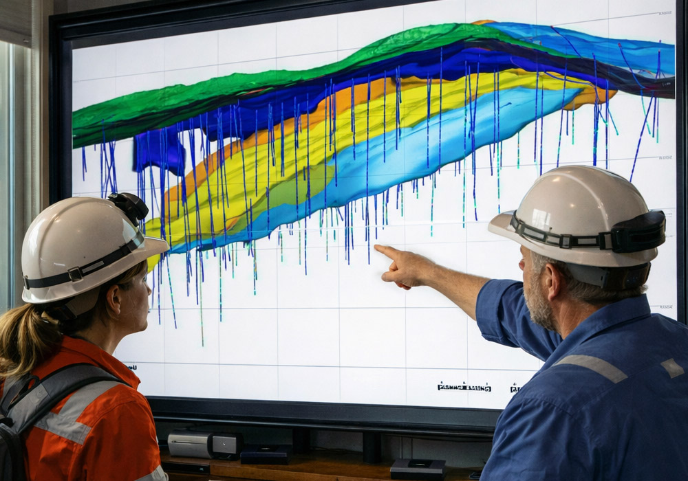
Geological interruptions like faults and dykes create additional constraints. A fault crossing a haulage way may require machinery to navigate a step in the floor, a change in drive direction, or a zone of poorer ground quality. These features are often known from geological modeling before development reaches them, which means that machinery specified early in the mine’s development cycle can account for them if the specification process includes the relevant geological input.
Drive Width and Turning Radius Revisited
Beyond the working face, the geometry of the development drives that connect to it determines the mobility requirements for all haulage machinery. Drive width determines the maximum machine width. Intersection geometry determines the turning radius machinery has to achieve.
These two parameters interact in ways that can be non-obvious. A drive that seems wide enough may have an intersection geometry that requires a tighter turn than a machine of that length can make. A machine that fits the drive width may still not be able to navigate the layout without multi-point turns that add time to every cycle.
The right combination of machine length, wheelbase, and articulation to navigate a specific mine’s development layout is a specification exercise that requires the actual mine plan, not a generic assumption about typical underground geometry. Mining equipment built without that input frequently requires the operation to work around its mobility limitations throughout its operational life.
How This Shapes the Custom Build Process
Custom fabrication starts from the site’s actual geological and development data because that’s what drives the specification. A mine’s headroom data, dip profiles, drive widths, and intersection geometries all feed into the design before fabrication begins. The result is machinery sized and configured for the specific operation rather than for a generalized underground application.
That approach matters most in operations where the geometry is unusual, variable, or both, because those are exactly the conditions where the gap between a custom build and a catalog product shows up most clearly in daily operations.
Conclusion
Ore body geometry isn’t a backdrop for underground operations. It’s an active design input that determines what machinery can enter the mine, how it has to perform once it’s there, and how reliably it can do that work over the life of the operation. Treating it as the starting point for the specification process, rather than a constraint to accommodate after the fact, is what produces machinery that genuinely fits the application it was built for.